Tuesday, November 24, 2015
VER 2.5 PROCESSORS ARE AVAILABLE.
Ver 2.5 processors are available. By changing out two zener diodes and adding a resistor to pin 15 on the control board will increase the weld energy from 600Ws to 800Ws. VER 2.5 Processor can work with 20V capacitors by removing the resistor on Pin 15 but the diodes should not be replaced until 25V capacitors are installed. UPDATE: JANUARY 5th 2016: 25V computer grade capacitors are hard to get at the moment. A Chinese company manufactured a couple of 1Farad 25VCapacitors for me. These Capacitors are heavy duty and very well built. I tested them and are great, 1.070 Farad with a 0.001 ESR. I can get them for a special price of $45 each. The shipping is expensive though and can only be shipped with DHL for $104. Contact me for more information to order these capacitors.


CAPACITOR DISCHARGE PCB's AND DOCUMENTS ARE AVAILABLE

This store will close on August 17th 2017
We ship Internationally with USPS priority mail. For any countries not on the list please email me at sprbok@gmail.com


Friday, March 2, 2012
INTELLIGENT LIGHT SWITCH
I moved on to another project that I'm busy developing and it is an intelligent touch screen light switch that will know exactly how many people are in a room . This switch will have many user friendly features and will turn the light on and off when people enter or leave a room. It can be used in any room with one or more doors and will work with voltages from 90VAC to 277 VAC making it suitable for businesses and domestic use all over the world.
Many people ask me what the difference is between this switch and the passive infrared switches already available. Well, the switches available are really pathetic and resets a timer every time it sees you move. When it doesn't see you and the timer times out the light turns off. To turn the light back on you have to wave at it for 15 seconds before the light turns back on. When you leave a room the lights usually stays on for 30 minutes or more, wasting energy. My switch will count people enter or leaving a room and turn the light off when the last person leaves. It will have a full color AMOLED touch screen display that can be changed to fit the decor of the room, and many other settings to make it very user friendly including an optional WIFI connection.

Many people ask me what the difference is between this switch and the passive infrared switches already available. Well, the switches available are really pathetic and resets a timer every time it sees you move. When it doesn't see you and the timer times out the light turns off. To turn the light back on you have to wave at it for 15 seconds before the light turns back on. When you leave a room the lights usually stays on for 30 minutes or more, wasting energy. My switch will count people enter or leaving a room and turn the light off when the last person leaves. It will have a full color AMOLED touch screen display that can be changed to fit the decor of the room, and many other settings to make it very user friendly including an optional WIFI connection.

Sunday, July 10, 2011
A PEEK AT ALL THE FILES INCLUDED TO BUILD THIS WELDER
THE DOCUMENT BELOW SHOWS WHAT ARE INCLUDED IN THE DOWNLOADABLE PACKAGE.
UPDATE: THE MOSFET PCB OUTLINE FILE (.GKO)CAN NOW BE DOWNLOADED HERE.
UPDATE: THE MOSFET PCB OUTLINE FILE (.GKO)CAN NOW BE DOWNLOADED HERE.
Wednesday, June 1, 2011
ADJUSTING PULSE 1
Pulse 1 on this welder is to burn away oil and dirt and pulse two makes the actual weld. I have many guys telling me that they set pulse one much higher to get two welds in one. Unfortunately, that's not how it works. Pulse one will join the two metals lowering the resistance and the energy of pulse two will take the shortest path to the other electrode doing basically nothing. In other words, If a 3ms pulse is enough to adhere the metals being welded and you set pulse one to 3ms and pulse two to 12ms then you will get one weak weld formed by the 3ms pulse and not the 12ms pulse.
To make decent welds with a dual pulse welder you should turn pulse one off and find a voltage and pulse 2 setting that gives you good solid welds. Leave the welder on the determined voltage and set both pulse potentiometers to 0, adjust pulse one to a low setting and make a weld. Keep on adjusting pulse one higher until the metals starts to adhere, decrease pulse one potentiometer about 3%. Set pulse two to the determined setting above and you should get really good welds.
The size of your electrodes and cable to your electrodes makes a big difference. A 4 feet long #0 welding cable will give you twice the current than a 4 Feet #8 welding cable. Do not make your cables shorter than 4 feet though.
To make decent welds with a dual pulse welder you should turn pulse one off and find a voltage and pulse 2 setting that gives you good solid welds. Leave the welder on the determined voltage and set both pulse potentiometers to 0, adjust pulse one to a low setting and make a weld. Keep on adjusting pulse one higher until the metals starts to adhere, decrease pulse one potentiometer about 3%. Set pulse two to the determined setting above and you should get really good welds.
The size of your electrodes and cable to your electrodes makes a big difference. A 4 feet long #0 welding cable will give you twice the current than a 4 Feet #8 welding cable. Do not make your cables shorter than 4 feet though.
Friday, April 29, 2011
UPDATED FIRMWARE AND WELDER FILES AVAILABLE SOON
I've been working on a new version 2.5 firmware for the Capacitor Discharge Welder and also a package that will contain the newest firmware, gerber files, Bill of materials, manuals and an extra 6 pages to explain how the circuit works and trouble shooting procedures etc. I've included Version 2.1 and version 2.5 in case a bug shows up. Version 2.5 has a change to the charging system, taking the stress off mosfet Q4, slowing the charge intervals and two points on the control board can be jumped with a wire to change the maximum voltage of this welder from 20 to 23.2V. This will increase the energy of the welder from 600Ws to 807Ws. You will need 25V capacitors to use this feature and Diode D10 has to be changed. UPDATE: I'm busy doing some final tests on the firmware. I did not get a very big response about making everything available so I'm going to start by making the updated chips available


If you don't know how to program a processor, you can buy one of these programmers.
 This one is $34.95 : K8076 serial programmer
 This one is $69.95 : Cana USB programmer
It is as easy as starting the software supplied with the programmer, plug your microprocessor into the programmer, connect the programmer to your computer, load the Hex file and click on "write". It will only take a couple of seconds.


If you don't know how to program a processor, you can buy one of these programmers.
It is as easy as starting the software supplied with the programmer, plug your microprocessor into the programmer, connect the programmer to your computer, load the Hex file and click on "write". It will only take a couple of seconds.
Monday, April 4, 2011
NAVIGATION
HERE IS AN EASIER WAY TO NAVIGATE THIS BLOG, click on the links below and read the pages from the bottom, up:
THE BLOG STARTS HERE: PAGE 1
PAGE 2
PAGE 3
PAGE 4
PAGE 5
PAGE 6
THIS PAGE: PAGE 7
THE BLOG STARTS HERE: PAGE 1
PAGE 2
PAGE 3
PAGE 4
PAGE 5
PAGE 6
THIS PAGE: PAGE 7
Monday, February 14, 2011
Pulse Arc Update
My function generator which came a long way with me went up in a plume of smoke. I had to replace it and bought a Rigol DG1022. It's a nice generator but pricey. I am going to use this generator to play with different waves to see if I can get the correct waveforms for the pulse arc welder. I am thinking of designing a new board from scratch, its already halfway drawn on a piece of paper :). The Budget is also a little low on funds and I will start to buy components as soon as possible. This welder will use much smaller and easy to get capacitors.
These things take time and lots of work so don't expect to see it before the end of this year.
ROGER CARR LET ME KNOW THAT FUTURE ELECTRONICS SELLS THE IRFP2907PBF MOSFETS FOR $3.60, THANKS ROGER.UPDATE: FUTURE ELECTRONICS CHANGED THEIR PRICE TO $6.00.....DO NOT BUY FROM THEM!!!!
These things take time and lots of work so don't expect to see it before the end of this year.
ROGER CARR
Saturday, January 1, 2011
Wednesday, December 8, 2010
Saturday, November 27, 2010
PULSE ARC WELDS


The top three photos was taken when I just started playing with the pulses on the pulse arc welder. The top left photo is two washers welded together, the middle is two strands from a 12 gauge copper wire welded to a washer and the photo on the right is two strands of a 12 gauge wire that were held against the tungsten electrode while firing a 45ms pulse. The bottom two photos were taken after I managed to manipulate and change the pulses to give better welds. The plasma flame produced here is extremely hot.
I have made thousands of welds and adjustments to get this far and will keep on going until I get it to work perfectly. I accidentally made a plasma cutter that cuts through metal when I made the pulses continuous and also managed to weld a copper wire to aluminum.
I'm limited to the metals I have to do further tests however and will appreciate if someone with knowledge of these welders can help me with some advice. Email me at sprbok@gmail.com
Monday, November 15, 2010
PROCESSOR CONTROLLED PWM RELAY DRIVER SCHEMATIC

When a magnetic solenoid/relay is energized, a magnetic field has to be formed strong enough to pull the plunger in. When this plunger is pulled in, the power can be reduced to a much lower level to keep it in.
This really cool circuit can do the above. If you pull a line, straight down, just before U5 and then build the circuit on the left, you will have a pulse width controlled relay driver circuit that can handle two relays with a total current of 1.5 amps. There are DRV103 IC's that can handle 3 Amps and by changing your power supply to 3 amps, can pull in really big relays/solenoids.
These PWM relay drivers can be activated by supplying 3 to 5V on pin 8 of U2 and U3. The two red LED's will turn on when an over current or over temperature is detected and will shut the IC's down.
This circuit can be changed to drive 12V relays by changing R1 and R2 resistors on the power supply.
When 3 to 5V is supplied to pin 8 of one of the IC's It will turn on fully, supplying 24V to the relay/solenoid and 22milliseconds later (C4 andC5) will start to pulse the voltage at 5000Hz (R3 and R4) and the duty cycle can be changed by adjusting R5 and R6.
R3 and R4 can be changed to get a different frequency, C4 and C5 can be changed if the relay/solenoid needs more time to pull in before a pulsed signal is supplied, just check out the data sheets.
How to adjust:
Put a voltage of 3 to 5V on pin 8 of the DRV103 IC. When the relay pull in, adjust R5 or R6 until the relay fall out. Set it back a little and energize it again to see if it stays in. If the relay doesn't want to pull in at all then replace C4 and/or C5 with bigger capacitors.
THE GERBER FILES FOR THIS BOARD CAN BE DOWNLOADED HERE
Thursday, November 4, 2010


Friday, October 22, 2010
PULSE ARC WELDER PCB BOARD
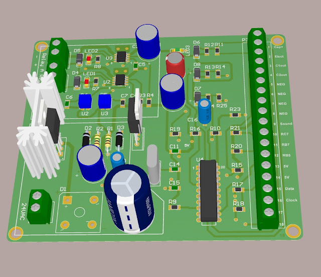 This is the prototype board, 4 X 4 inches, that will be driving the Argon and electrode solenoids of the pulse arc stylus.
The white block, printed on the board, in the bottom left corner is the 24VDC power supply and the block at the top left corner is the PWM relay drivers. The area on the rights is the microprocessor circuit.
The microprocessor is going to do a lot of things. It will determine if the electrode is touching the work piece, activate the argon solenoid, calculate the time when to give a pulse to the PWM relay driver circuit to retract the electrode, produce a couple of bleeps and give a pulse to start a pulse arc weld.
This processor will also talk to the other processor in the capacitor discharge welder to make energy pulses possible and much much more.
The PWM relay driver will supply 24V to the relay/solenoid and 22Ms (adjustable) later will give a pulsed adjustable duty cycle. This will reduce the current, preventing the solenoids and electronic driving circuits from overheating.
I'm waiting for the components and boards at the moment and will start doing some test welds soon.

The white block, printed on the board, in the bottom left corner is the 24VDC power supply and the block at the top left corner is the PWM relay drivers. The area on the rights is the microprocessor circuit.
The microprocessor is going to do a lot of things. It will determine if the electrode is touching the work piece, activate the argon solenoid, calculate the time when to give a pulse to the PWM relay driver circuit to retract the electrode, produce a couple of bleeps and give a pulse to start a pulse arc weld.
This processor will also talk to the other processor in the capacitor discharge welder to make energy pulses possible and much much more.
The PWM relay driver will supply 24V to the relay/solenoid and 22Ms (adjustable) later will give a pulsed adjustable duty cycle. This will reduce the current, preventing the solenoids and electronic driving circuits from overheating.
I'm waiting for the components and boards at the moment and will start doing some test welds soon.
Sunday, September 12, 2010
PULSE ARC WELDING STYLUS


I machined this stylus with my lathe and CNC mill out of aluminum. It compares to the Sunstone Engineering Orion HERE and the PUK 3 pulse arc welders that can weld gold, silver, aluminum, copper, steel, nickel etc. The stylus has a solenoid that retracts the tungsten electrode to start and sustain a very hot plasma arc and argon gas to shield the weld like a TIG welder. This plasma arc is used as a heat source to melt the metal together. Filler rod can also be used to make strong and reliable welding seams.
Saturday, August 7, 2010
A123 UPDATE
These welders have many variables and depending on the size cables, probes and capacitors you used etc. will determine your weld settings. I have done hundreds of welds on A123 batteries and determined that they are no different from any other batteries. When your tabs are too thick to make decent welds, you have to improvise. Current always takes the easiest path and by making dimples and a cut in the middle (picture below) on the tab you are welding will force the current into one dimple, through the battery and out the other dimple. Concentrating the heat on the dimples and produce very strong welds.

You can punch your own dimples and use two pieces of nickel like the picture below.
 The probes are also very important, don't use probes with flat tips unless you have a weld head that pushes the probes perfectly flat on the piece that gets welded. Make your tips round on a lathe with a file, like the microscope pictures of my probes below and then use very fine sanding paper to smooth the tips. Rounded tips will make perfect welds every time, won't stick and you can hold the probes at almost any angle.


You can punch your own dimples and use two pieces of nickel like the picture below.


Sunday, July 25, 2010
PULSE ARC WELDING
I'm looking into adding pulse arc welding to this welder. Pulse arc welding is like TIG welding. By adding Argon gas through a special gun with a tungsten tip will produce a very hot plasma arc that will melt almost any metals together( including aluminum, gold and silver). This welder was originally designed to use a contactor and can easily be converted to activate an argon gas solenoid and a retractable tungsten tip. I will appreciate any input.
Saturday, July 3, 2010
ESR TEST AND A123 CELLS
I have measured the ESR of my welder and its much lower than anticipated. The ESR of the welder bus bars at the front of the welder measures less than 0.0005 Ohm (500 micro Ohm). With such low resistance, this welder can produce astronomical currents and will only be limited by the resistance of the probe, wire and material being welded.
I am way behind schedule with my version 3 processor and spent most of my time getting the new welder built.
Most companies and people out there that are welding A123's are very tight lipped about how they do it and I would like to get to the bottom of it!!! I'm doing some experiments with inverted resistance welding and was wondering if there are some of you guys that would send me some of your old A123's to play with ??? I will post all my findings on here!!!
I am way behind schedule with my version 3 processor and spent most of my time getting the new welder built.
Most companies and people out there that are welding A123's are very tight lipped about how they do it and I would like to get to the bottom of it!!! I'm doing some experiments with inverted resistance welding and was wondering if there are some of you guys that would send me some of your old A123's to play with ??? I will post all my findings on here!!!
Wednesday, June 23, 2010
NEW WELDER
I started my new welder up today and did a couple of test welds. The welds look really good and much better than my previous welder. I welded some copper to a washer at very low voltages and also checked to see how fine the settings can go by welding 80 micron gold plated tungsten wire to a washer (the photo below was taken with my microscope) and I placed a small BC 847 surface mount transistor next to it. My probe tips are all messed up and I am busy cutting new ones with my lathe which will make much better looking welds. I will also test the ESR this weekend and I'm hoping that it will be in the 0.001 to 0.0015 Ohm range.


Saturday, June 12, 2010
WELD POLARITY
I have many guys asking me why their welders burn holes every now and then and what the big deal is about the polarity of the probes.
Resistance = heat, meaning that the higher your resistance, the more heat you will have. Probe pressure is very important and the harder you push on the probes the better it will make contact and the lower your resistance will be, causing welds that are colder and with too much pressure too cold to melt the metals together. If the probe pressures are not firm enough, it will cause a higher resistance causing too much heat and burn holes. That is why many companies that sells these welders have Weld Heads that are adjustable and make welds when a settable pressure is achieved. That does not mean that we cannot make any good welds by holding the probes in our hands.
Polarities are also very important. when a weld is made it forms a nugget between the metals being welded. This nugget is the melted metal between the two metals that joins them together and you want this nugget to be in the middle of the metals being welded.
When you do a weld the nugget gets attracted to the positive electrode more than the negative electrode and also gets attracted to the metal with the higher resistance. When you weld copper and steel together the nugget will form in the steel with the higher resistance and little or nothing will form in the copper making the copper not stick to the steel or a very weak weld.

A way to move the nugget to the middle of your weld is to always put your positive electrode on the material with the lowest resistance, like copper and your negative electrode on the steel with the higher resistance. If you weld thick and thin metals together you will have to put your positive electrode on the thicker material(thick metals take longer to melt) and your negative on the thinner material. 

By looking at the photo below, we can clearly see the electrode positions.

The welds at the bottom of the "stock welds" and " My welds"(I got this pic from a guy that bought one of my boards) are deeper than the top ones and kind of went through the metal, making them weak welds. The positive electrodes were at the bottom of these welds and the negative electrodes were at the top. To overcome the deep welds at the bottom you have to put more pressure on the bottom probes (making colder welds) and put less pressure on the top probes (more resistance = more heat which will make deeper welds).


Subscribe to:
Posts (Atom)