Wednesday, December 8, 2010
Saturday, November 27, 2010
PULSE ARC WELDS


The top three photos was taken when I just started playing with the pulses on the pulse arc welder. The top left photo is two washers welded together, the middle is two strands from a 12 gauge copper wire welded to a washer and the photo on the right is two strands of a 12 gauge wire that were held against the tungsten electrode while firing a 45ms pulse. The bottom two photos were taken after I managed to manipulate and change the pulses to give better welds. The plasma flame produced here is extremely hot.
I have made thousands of welds and adjustments to get this far and will keep on going until I get it to work perfectly. I accidentally made a plasma cutter that cuts through metal when I made the pulses continuous and also managed to weld a copper wire to aluminum.
I'm limited to the metals I have to do further tests however and will appreciate if someone with knowledge of these welders can help me with some advice. Email me at sprbok@gmail.com
Monday, November 15, 2010
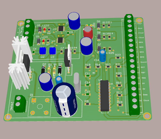
PROCESSOR CONTROLLED PWM RELAY DRIVER SCHEMATIC

When a magnetic solenoid/relay is energized, a magnetic field has to be formed strong enough to pull the plunger in. When this plunger is pulled in, the power can be reduced to a much lower level to keep it in.
This really cool circuit can do the above. If you pull a line, straight down, just before U5 and then build the circuit on the left, you will have a pulse width controlled relay driver circuit that can handle two relays with a total current of 1.5 amps. There are DRV103 IC's that can handle 3 Amps and by changing your power supply to 3 amps, can pull in really big relays/solenoids.
These PWM relay drivers can be activated by supplying 3 to 5V on pin 8 of U2 and U3. The two red LED's will turn on when an over current or over temperature is detected and will shut the IC's down.
This circuit can be changed to drive 12V relays by changing R1 and R2 resistors on the power supply.
When 3 to 5V is supplied to pin 8 of one of the IC's It will turn on fully, supplying 24V to the relay/solenoid and 22milliseconds later (C4 andC5) will start to pulse the voltage at 5000Hz (R3 and R4) and the duty cycle can be changed by adjusting R5 and R6.
R3 and R4 can be changed to get a different frequency, C4 and C5 can be changed if the relay/solenoid needs more time to pull in before a pulsed signal is supplied, just check out the data sheets.
How to adjust:
Put a voltage of 3 to 5V on pin 8 of the DRV103 IC. When the relay pull in, adjust R5 or R6 until the relay fall out. Set it back a little and energize it again to see if it stays in. If the relay doesn't want to pull in at all then replace C4 and/or C5 with bigger capacitors.
THE GERBER FILES FOR THIS BOARD CAN BE DOWNLOADED HERE
Thursday, November 4, 2010

Friday, October 22, 2010
PULSE ARC WELDER PCB BOARD
 This is the prototype board, 4 X 4 inches, that will be driving the Argon and electrode solenoids of the pulse arc stylus.
The white block, printed on the board, in the bottom left corner is the 24VDC power supply and the block at the top left corner is the PWM relay drivers. The area on the rights is the microprocessor circuit.
The microprocessor is going to do a lot of things. It will determine if the electrode is touching the work piece, activate the argon solenoid, calculate the time when to give a pulse to the PWM relay driver circuit to retract the electrode, produce a couple of bleeps and give a pulse to start a pulse arc weld.
This processor will also talk to the other processor in the capacitor discharge welder to make energy pulses possible and much much more.
The PWM relay driver will supply 24V to the relay/solenoid and 22Ms (adjustable) later will give a pulsed adjustable duty cycle. This will reduce the current, preventing the solenoids and electronic driving circuits from overheating.
I'm waiting for the components and boards at the moment and will start doing some test welds soon.
Sunday, September 12, 2010
PULSE ARC WELDING STYLUS


I machined this stylus with my lathe and CNC mill out of aluminum. It compares to the Sunstone Engineering Orion HERE and the PUK 3 pulse arc welders that can weld gold, silver, aluminum, copper, steel, nickel etc. The stylus has a solenoid that retracts the tungsten electrode to start and sustain a very hot plasma arc and argon gas to shield the weld like a TIG welder. This plasma arc is used as a heat source to melt the metal together. Filler rod can also be used to make strong and reliable welding seams.
Saturday, August 7, 2010
A123 UPDATE
These welders have many variables and depending on the size cables, probes and capacitors you used etc. will determine your weld settings. I have done hundreds of welds on A123 batteries and determined that they are no different from any other batteries. When your tabs are too thick to make decent welds, you have to improvise. Current always takes the easiest path and by making dimples and a cut in the middle (picture below) on the tab you are welding will force the current into one dimple, through the battery and out the other dimple. Concentrating the heat on the dimples and produce very strong welds.

You can punch your own dimples and use two pieces of nickel like the picture below.
 The probes are also very important, don't use probes with flat tips unless you have a weld head that pushes the probes perfectly flat on the piece that gets welded. Make your tips round on a lathe with a file, like the microscope pictures of my probes below and then use very fine sanding paper to smooth the tips. Rounded tips will make perfect welds every time, won't stick and you can hold the probes at almost any angle.


You can punch your own dimples and use two pieces of nickel like the picture below.


Sunday, July 25, 2010
PULSE ARC WELDING
I'm looking into adding pulse arc welding to this welder. Pulse arc welding is like TIG welding. By adding Argon gas through a special gun with a tungsten tip will produce a very hot plasma arc that will melt almost any metals together( including aluminum, gold and silver). This welder was originally designed to use a contactor and can easily be converted to activate an argon gas solenoid and a retractable tungsten tip. I will appreciate any input.
Saturday, July 3, 2010
ESR TEST AND A123 CELLS
I have measured the ESR of my welder and its much lower than anticipated. The ESR of the welder bus bars at the front of the welder measures less than 0.0005 Ohm (500 micro Ohm). With such low resistance, this welder can produce astronomical currents and will only be limited by the resistance of the probe, wire and material being welded.
I am way behind schedule with my version 3 processor and spent most of my time getting the new welder built.
Most companies and people out there that are welding A123's are very tight lipped about how they do it and I would like to get to the bottom of it!!! I'm doing some experiments with inverted resistance welding and was wondering if there are some of you guys that would send me some of your old A123's to play with ??? I will post all my findings on here!!!
Wednesday, June 23, 2010
NEW WELDER
I started my new welder up today and did a couple of test welds. The welds look really good and much better than my previous welder. I welded some copper to a washer at very low voltages and also checked to see how fine the settings can go by welding 80 micron gold plated tungsten wire to a washer (the photo below was taken with my microscope) and I placed a small BC 847 surface mount transistor next to it. My probe tips are all messed up and I am busy cutting new ones with my lathe which will make much better looking welds. I will also test the ESR this weekend and I'm hoping that it will be in the 0.001 to 0.0015 Ohm range.


Saturday, June 12, 2010
WELD POLARITY
I have many guys asking me why their welders burn holes every now and then and what the big deal is about the polarity of the probes.
Resistance = heat, meaning that the higher your resistance, the more heat you will have. Probe pressure is very important and the harder you push on the probes the better it will make contact and the lower your resistance will be, causing welds that are colder and with too much pressure too cold to melt the metals together. If the probe pressures are not firm enough, it will cause a higher resistance causing too much heat and burn holes. That is why many companies that sells these welders have Weld Heads that are adjustable and make welds when a settable pressure is achieved. That does not mean that we cannot make any good welds by holding the probes in our hands.
Polarities are also very important. when a weld is made it forms a nugget between the metals being welded. This nugget is the melted metal between the two metals that joins them together and you want this nugget to be in the middle of the metals being welded.
When you do a weld the nugget gets attracted to the positive electrode more than the negative electrode and also gets attracted to the metal with the higher resistance. When you weld copper and steel together the nugget will form in the steel with the higher resistance and little or nothing will form in the copper making the copper not stick to the steel or a very weak weld.

A way to move the nugget to the middle of your weld is to always put your positive electrode on the material with the lowest resistance, like copper and your negative electrode on the steel with the higher resistance. If you weld thick and thin metals together you will have to put your positive electrode on the thicker material(thick metals take longer to melt) and your negative on the thinner material. 

By looking at the photo below, we can clearly see the electrode positions.

The welds at the bottom of the "stock welds" and " My welds"(I got this pic from a guy that bought one of my boards) are deeper than the top ones and kind of went through the metal, making them weak welds. The positive electrodes were at the bottom of these welds and the negative electrodes were at the top. To overcome the deep welds at the bottom you have to put more pressure on the bottom probes (making colder welds) and put less pressure on the top probes (more resistance = more heat which will make deeper welds).


Tuesday, May 25, 2010


Friday, May 21, 2010
UPDATE
I was promised a case for my welder but it seems like I'm not going to get it after a 5 month wait. I decided to buy the 12 X 12 X 19 case from mouser ($140 including shipping and taxes) HERE. This case is bigger than what I need but I guess it will do for now. I'm going to cut out the face with my CNC milling machine this weekend and rebuild all the circuitry into the new box.
I did some tests on my welder to determine the ESR and Max weld current. I connected 3 X 1 Farad computer grade capacitors with #8 welding cable and got an ESR of 0.0020mOhms. At 20V you will get 10 000 amps. The Mosfet board can handle 15 000 Amps and by using bigger cable, copper bus bars and better connections can increase the current to give you much better and deeper welds than Sunstone Engineering can ever give you for $8000
I did some tests on my welder to determine the ESR and Max weld current. I connected 3 X 1 Farad computer grade capacitors with #8 welding cable and got an ESR of 0.0020mOhms. At 20V you will get 10 000 amps. The Mosfet board can handle 15 000 Amps and by using bigger cable, copper bus bars and better connections can increase the current to give you much better and deeper welds than Sunstone Engineering can ever give you for $8000
Friday, April 16, 2010
New Version3 MicroProcessor
I have been working very hard on a Version 3 Microprocessor for this welder. Version 3 will change this welder from timed pulses to energy pulses. Energy pulses will give you more control of your weld by calculating and adjusting the pulse width automatically to the resistance that you are welding, preventing burned holes due to the wrong probe pressure and a change of resistance. This processor will also have features showing the capacitance of your capacitor and a feature to change the max voltage to 24V.
Tuesday, March 30, 2010
Friday, March 5, 2010
MOSFET PCB's ON ORDER

If you look at the board it is hard to believe that it is 3oz copper but by running your fingers over the edges of the copper you can feel the the difference. The board is also heavier. The camera and lights make the silver color on this board look like it is copper.
Tuesday, March 2, 2010
Saturday, February 27, 2010
BUG!!!!!
I have a couple of guys that successfully build their welders and are happy with it. However, there is a little bug that showed up. This bug is in the programming that happened in a last minute change to one line of code before starting to ship the processors out. It is more of an annoyance than anything else. By turning your voltage pot up, the set point text on the display will stop at 20Volt. If you keep on turning the potentiometer past this point your capacitor will get charged to a higher voltage and the over voltage protection will kick in and trip U5. The capacitor voltage will start to drop. To reset U5, you have to lower the voltage set point below the actual dropping capacitor voltage and raise the set point up again. If you are rebuilding battery packs and are using a car capacitor, you would never need to go that high with your voltage but for those guys that would like this bug fixed, send me an email and we can work out a way to get your processor updated. Everyone that received boards and processors after 02/15/10 will have the newest firmware already.
Monday, February 15, 2010
Manufactured PCB's
I have placed an order for the Mosfet PCB's this morning. It had to be sent to an offshore facility because of the 3oz copper and will take about three weeks. I tried to order "OR" boards (some guys said that they will take 1 "or" 2 ) but they didn't have any :)) so I didn't get too many of the mosfet boards. I mentioned in a previous post that I got a price for a 3 layer board that would have solved the weak spot issue on the PCB but it was very expensive. This is a 2 layer board and It has 94 via's that connects the bottom and the top layer. The copper of the bottom and top layer together will be 0.0084" thick. I worked the price out to $80/board + shipping and will sell it on a first come first serve basis.
Friday, February 12, 2010
Manufactured Mosfet PCB
I changed the Mosfet PCB to a three layer board and I got quotes to have it manufactured. The price was really high, more than $120 per board. I went back to the drawing board and redesigned the 2 layer board to make it stronger with 3oz of copper (took me 2 days). I would just like to know how many of you guys will be interested in this board? The more I buy, the less expensive they get.


Thursday, February 4, 2010
SMD BOARD AVAILABLE

Wednesday, February 3, 2010

Saturday, January 30, 2010
Thursday, January 28, 2010


Saturday, January 23, 2010

Sunday, January 17, 2010
MOSFET PCB FILES ARE AVAILABLE AT THE BOTTOM OF THE PAGE

This is a photo that shows the 0.007" stainless steel weld
The mosfet PCB has been strengthened and works really good. I just received 0.007 stainless steel strips and welded it with just one weld to a crescent wrench with a voltage of 12V and a first pulse of 1.2Ms and a second pulse of 7.8 Ms. This weld is so strong that it is impossible to break with your bare hands. I'm going to make the control PCB's available to the people that gave me donations for this project first as promised.Saturday, January 16, 2010
Found It

We can see how powerful this welder is, It burned the copper. When I designed the Mosfet board I did add via's to connect the top and bottom layers to increase the load this board can take. At the place where it burned, I actually designed it to be connected with 4 wires (shown by the blue lines). The copper burned because it was connected vertically and not horizontally. I will include this in the manual and try to strengthen the copper more.
Thank you guys for all the suggestions about the cause of the copper burning. Everyone thinks that he knows best about what happened. THE PROBLEM AND THE CAUSE WAS FOUND AND REPAIRED. This welder was designed to work with a 3 farad Capacitor and at the time, had capacitors connected in parallel totaling 4.5Farads. The circuit at the top has a gate circuit that divides the top layer in 3 areas that needed to be connected with wires. These areas were not connected and it caused a weak spot on the copper. I took photos and explained in the manual what to do, to make the copper withstand higher current.
How do they say it in the movies?....no components were harmed with this incident :))
Friday, January 15, 2010
Capacitor Size
As you guys know, I have someone building one of my welders at the moment. He (Shawn) measured the capacitance of his capacitor and came out way short (He is sending it back). Shawn connected 3 capacitors in parallel with a total of 4.5 Farads. He said that the welder worked really good until he cranked it up to 18V with a first pulse of 30Ms and a second of 35Ms when he heard a "pop", That was after about 18 welds. We are trying to find out what went wrong and are in a process of pinpointing the problem. The first pulse is basically just to burn away oil and dirt and the second pulse is the one that does the actual weld. 30Ms for a first pulse is way too high and It might have something to do with the popping sound. When we find the problem, I will redesign and make sure that this never happens again. Hang in there guys, I will keep you updated.
Wednesday, January 6, 2010
Welder Case


Shawn sent these photos to show how his welder is progressing. These photos also show the case that we might make available if you guys are interested. He still has to work out what it will cost to make one of these and we might ship them out in different stages of manufacture to make it less expensive, meaning with or without paint, etc. He is hoping to get his welder up and running by next week. Thanks Shawn, it looks awesome!!
Friday, January 1, 2010
Happy new year everyone!!!!
Thanks for all the support, e-mails and comments Guys. I took some time off to spent with my family over the festival season and are back to finish this project. I have a guy with the name of Shawn building this welder at this moment and I'm using his feedback and questions to write a manual with trouble shooting tips to help with the construction of this circuit. I am busy with the last part of this welder, the Mosfet circuit, and are making it smaller and lining the mounting holes up so the controller board can be mounted on top of the Mosfet board.
For the people that donated, at the bottom of the page, you guys are first on my list! I will be using this money to buy more boards and processors and have it available. THANKS GUYS
I have a very small group of people that are part of this blog and will let you guys have the first choice too.
THANKS GUYS, AND A HAPPY 2010 TO YOU ALL!!!!
Subscribe to:
Posts (Atom)